Last updated 2012-12-28
Editorial note: When I originally wrote this page in the 20th century, I included all measurements in metric and imperial units. When I re-wrote it in 2012, I decided to delete the imperial units. If you still can't handle metric units, maybe it's time to learn! Only three countries now use those horrible units. One is a totalitarian regime in southeast Asia. Another is a totalitarian regime in west Africa. The third is in North America, and has actually been officially metric since the 1880s.
The station described in this section is sadly no longer. The towers are still up, but very little works. Some cables have been stolen (for the scrap value of copper!) and some bits and pieces have just degraded due to age.
At the moment (2012), only three antennas work. The tribander near the house works well, and is also pressed into service for 12 and 17 m (25 and 18 MHz). A few quarter-wave slopers with a common feedpoint hang off the low-band tower, with the apex somewhere around 35 m. Finally, there is a 5 element Yagi for 50 MHz which stands on a 5 m pole near the house, fixed north.
I have only one radio: An IC706 without CW filters. Please have some empathy for the operator at the end of all those low band contacts. The radio drives an amplifier to about 400 W output, but the barndoor-wide receiver filters cause considerable pain.
A Pentium One vintage computer running MMTTY is used for RTTY. I use the radio's FSK modulator, so I can't use any of the other fancy digital modes.
I am not making an attempt to get the station working again, as I will eventually sell and move. I've bought another hilltop on about 12 ha of land, further from the city of Pretoria. At the moment, my main project is to try and pay for the land while looking for a buyer for this place. Once I've done that, I'll start thinking about buildings and antennas.
Maybe I'm not quite being truthful. I am actually thinking about antennas again after taking a break of more than a decade to raise my daughter. Most of the thinking revolves around high-performance low band antennas.
Before other commitments took their toll and urban development encroached on me, I had great plans for this place. For a short while around 2000, I even had a great station.
The station is on about 1,1 ha (3 acres) of land, on a ridge overlooking Pretoria. The nearest suburb was originally about 3 km away, but development has now sprung up all around. The nearest high-density dwellings are just across the street now. Terrain drops off gently in most directions, including the most important ones for contesting. It's not perfect, but it's several dB better than a flat plane at the antenna heights that I use. I bought the land vacant, and built two houses on the property. I live in the smaller of the two houses, while the other is occupied by tenants. For some years, one of those tenants was my long-time radio buddy Hal Lund ZS6WB.
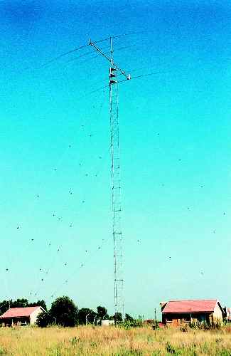
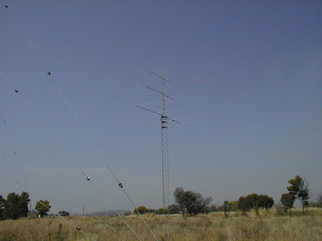
A global view of the station, from the south, taken around 1998. The rental house is on the right, while I live in the house on the left. The tower is 42 m tall, with the big beam at 36 m. The beam has 2 elements on 80, and 3 on 40. There is an independent rotating mast above the big Yagi. At one time, ZS6WB had a 50 MHz beam with independent rotation there, 42 m high. This Yagi was a real band-opener, and is visible in the picture below.
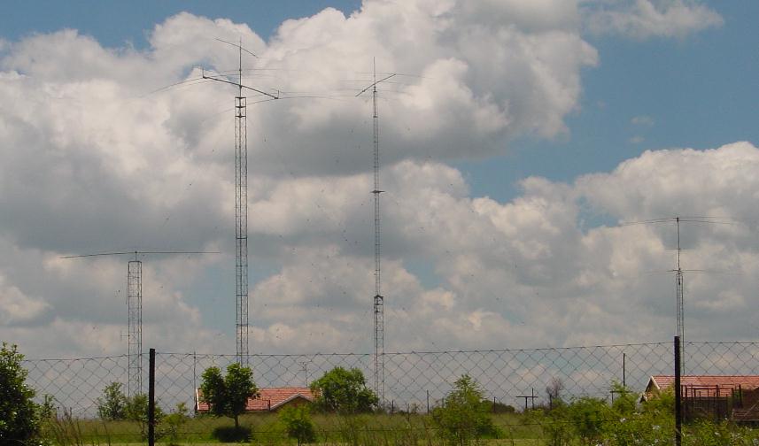
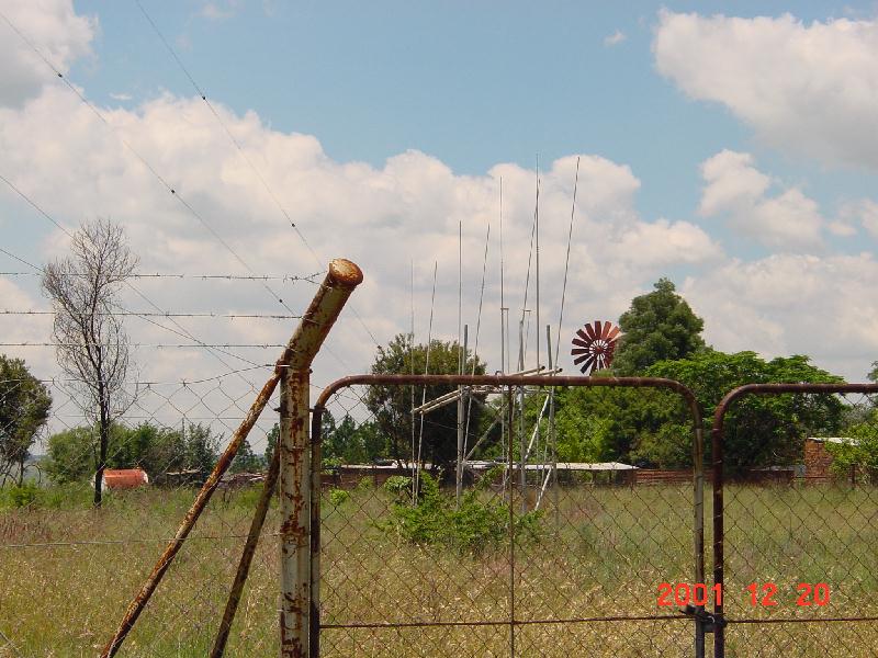
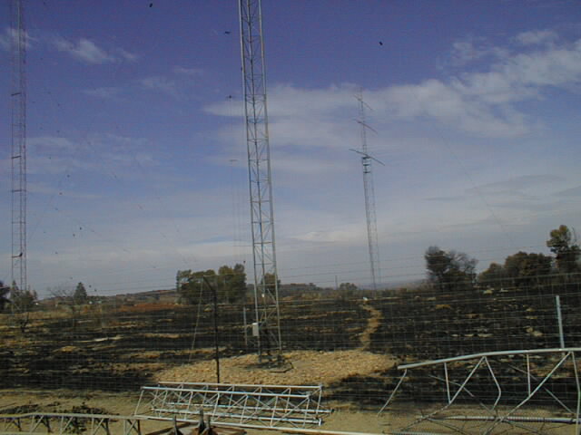
A wider view, taken around the end of 2001. The towers, in the usual order, are: Hal's long-boom 50 MHz beam at 18 m; the low band tower; the high band tower; the one-size-fits-all tower. The EME tower is not visible. This picture was taken by ZS4TX from the road, looking south-east. Because of the distance, the depth is hard to discern. The high band tower is furthest south, and furthest from the camera. The two small towers are furthest north, and closest to the camera. The small tower on the right is 22 m tall and supports a Force 12 C3 tribander (which also covers WARC bands with a bit of coaxing) and a defunct 2 element Shorty Forty. The entire tower was fed as a low band vertical once upon a time. ZS4TX photo, 2001-12.
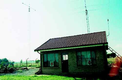
This is the house I live in. Since the picture was taken, I've added a small music room to the left, specifically to accommodate my Steinway grand. There is a small radio room, but a second operating position can be installed in the lounge for multi-op efforts. The trailer on the left is over 7 m long, and was used to transport antenna hardware, both for construction purposes and for DXpeditions. You may recognise this trailer from many DXpedition magazine articles: 3DA0Z, 3DA0/ZS6BCR, 3DA0/G3SXW, 3DA0/G3TXF, 3DA0/G4FAM, 3DA6Z, 7P8EN, V51Z, ZS0Z, ZS3Z, ZS9Z and others.
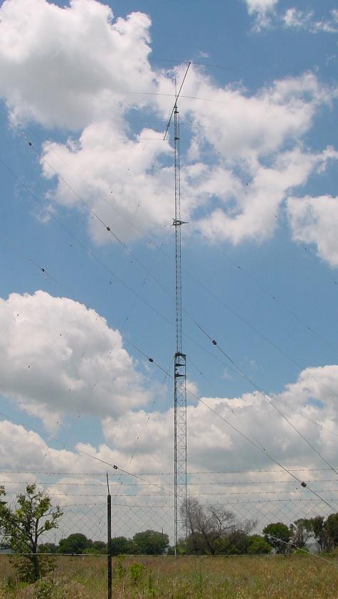
The high band tower's stationary portion is 17 m tall. Everything above that point, up to 45 m, rotates. The wide-spaced four element beam for 14 MHz sits at about 42 m. Once upon a time, this tower featured this beam plus a two-high stack for 21 MHz and a three-high stack for 28 MHz. An early manifestation of this tower can be seen below in the 1999 pictures. ZS4TX photo, 2001-12.
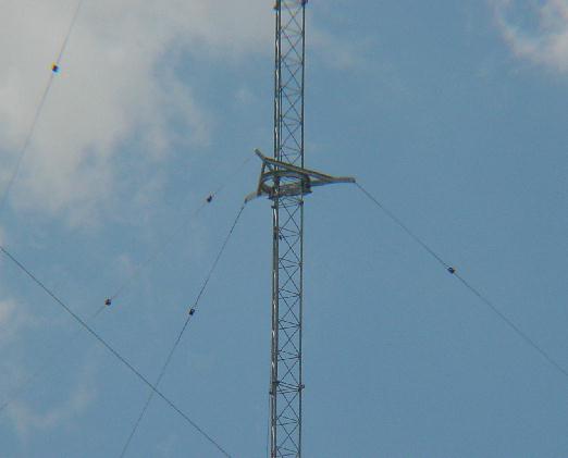
The rotating ring is home-made, as our currency's weakness makes imported stuff obscenely expensive. Each corner of the tower has two rollers, a vertical one inside and a horizontal one below the ring. The rollers are machined from Vesconite, a synthetic bearing material, with stainless steel bushes around them. The ring assembly weighs around 50 kg. ZS4TX photo, 2001-12.
The fifth tower never quite made it past the construction phase. It was planned to be 14 m tall, and would support a 144 MHz EME array. Right now, this tower serves as a storage stand for my spare 28 MHz beams. Grass fires are a regular occurrence, and you don't want your beams lying in the grass when a fire starts! ZS4TX photo, 2001-12.
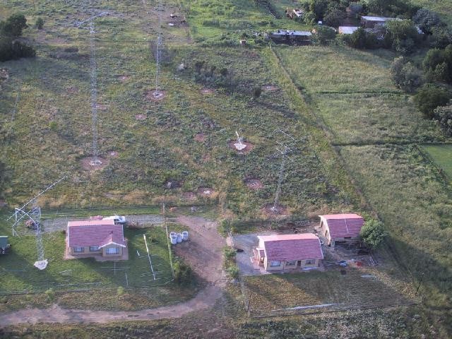
A few weeks after putting up these pictures of my station, I was rudely awakened at the crack of dawn one morning, by the cacophony of a lawnmower chasing a beach umbrella above my house. Later in the day, I discovered that Danie Brynard ZS6AWK had been the culprit, circling low above my house in his microlight aircraft while decent people are still asleep. Danie made up for it by taking this picture, though. It really shows the station nicely! The rental house is on the left, with ZS6WB's tower in the lower left corner. Behind his house is the low band tower. The bottom half of the high band tower can be seen in the middle background, with the six anchor points around it. On the right are my house and the workshop/storeroom, and behind it the small all-purpose tower. The triangular concrete block is the base for the EME tower. My property boundaries are all visible, along the left and lower edges of the picture, behind the store on the right, and just below the 80 m beam. The picture was taken looking roughly south. On the west (right) is an ostrich farm, and on the south (far end) is a horse farm. The rest was low-density residential, but a creche for toddlers has subsequently sprung up to the northeast. Finally, the long shadows towards the west indicate that it's still time for sane people to be in bed. The 28 MHz long-boom Yagi (10M7) is lying just to the right of Hal's house, with two 10M4 Yagis supported by the EME tower. Another 15M4 hides in the grass near the HF tower, while another 15M4, another 10M4, a 15M6, a 10M3 and an A4S lie in various stages of assembly around my house. ZS6AWK photo, 2002-01.
I dunno; ask Frank Zappa! However, to help you make up your mind, I present these pictures that DK3GI took in September 1999.
While on a business trip to our area, Roland visited my station on two successive weekends. In the intervening week, there had been a rampant grass fire that destroyed all vegetation and came very close to the houses (the scrap tower section in the "After" picture lies right next to the garage!). A neighbour's house was razed to the ground. Roland later emailed me these two photographs with the comment, "No, you don't need a bigger amplifier!".
I wish!
The two photos also show the third tower, with four element Yagis for 14, 21 and 28 MHz (15 m, 11 m and 8 m booms respectively). This tower has now been extended into the rotating tower shown above. It provided sterling service, as my 28 MHz stack for the 1999 and 2000 contest seasons lived on this tower.
The guy rings are made from 100 x 50 x 8 mm channel, rolled into a circle about 1 m in diameter. The guy attachments are made from 10 mm steel. The bearings run on 25 mm stainless spindles, and are 50 mm in diameter. They are made from Vesconite, a synthetic bearing material that can run with or without lubrication. The spindles sit in a cradle fabricated from 10 mm steel.
John Brosnahan W0UN showed me some design ideas when I visited his station during 1995, but the cam followers that he uses are around six times more expensive than my solution. The Vesconite bearings look like a great idea, provided that they hold up in practice!
The rotating tower exerts a force of around 3 tonnes on its base, because of the weight of the tower itself and the antennas, and because of the tension in the guy lines. I could not find a flange bearing capable of holding a 3 tonne axial load, so I had to design a holder for a suitable tapering bearing. The lower portion of the mast is held in a standard flange bearing. The upper bearing sits on a 20 mm plate, supported by 12 mm gussets, at a height of 17 m. The lower bearing's flange is bolted to a 12 mm plate, and the rotator sits off-centre on a 6 mm plate below it. The tower is driven through an industrial-grade chain drive. The Orion OR2800P I had there was fine for the free-standing tower, but the guyed rotating tower needs something more beefy. One day, a prop-pitch motor will be installed as soon as the metalwork modifications have been completed.
I've had mixed results with the Orion rotors. Apart from the one in the rotating tower, I have one in the tall tower turning the low band Yagi, too. This rotor's neck broke some months after installation, due to the sideways load exerted by the cable drive I was using at the time. I was surprised, as by design the tension in the cable was well below what would result from a load corresponding to the maximum advertised wind load, even if mounted exactly at the clamp's upper surface (i.e. the most favourable condition for the rotor). Nevertheless, I had to pay for a replacement shaft from the factory. Apart from replacing the splined shaft, I also had to make extensive modifications to the tower to include another bearing, thereby removing all sideways force from the rotator shaft. All this complication would have been unnecessary if the shaft had actually met its rated load. Drilling 20 mm holes in a 20 mm plate, 11 storeys above Mother Earth, is a process that has to be tried to be appreciated. My then colleague Jan Grobbelaar helped me gladly, but swore that he would never venture onto that tower again!
One of my controllers has also malfunctioned intermittently over a period of four years. Problems came and went intermittently, and no amount of trying could fix those problems. They sometimes just disappeared after a month or two, but later became more persistent. As it took a long time to get circuit diagrams, I had to send the controller board back to the factory, twice. It could have been something silly like a loose chip socket, but without troubleshooting info I had no way of telling. Also, two controllers (for use with prop pitch motors) were delivered faulty or incomplete, and replacement parts had to be ordered from the factory.
However, when they work, the OR2800Ps are great. I had my presets programmed in 30 degree increments, so that I can turn the stack during a contest by just punching the button the relevant number of times. Going from thirty to 300 degrees, for example, merely involves punching the "CCW" button three times, and then continuing the pileup. The rotator ramps up to full speed, finds the correct heading and ramps down to zero, all without further intervention from me.
Building a radio station, to my way of thinking, involves mainly tower work, concrete and subterrainean pipes. Novices generally tend to get excited about what's in the shack, but I feel that one can always fix that later. The important thing is to have the right hardware in the sky. The rest is details.
However, at a sufficiently competitive level, details also become important. With the cutthroat competition that exists in DX contesting these days, two-radio operation is a must. One must be able to run stations, calling CQ continuously, while also looking for multipliers. Two-radio techniques are useful, in that they allow this process to take place on two bands simultaneously. With several single-band antennas and the necessary filtering, an operator can tune for (and work!) multipliers on another band while running a frequency.
However, to look for multipliers on the same band is a different ballgame. Sophisticated interlocking is required to prevent the second receiver's front end from going up in smoke. Fortunately, radio designers have seen this need and have addressed it by including second receivers in top-line radios. The IC781 was probably the first mass-marked radio to include two receivers, and remained on the market for well over a decade. The IC756 and other Icoms also included this arrangement. However, to my mind the Icom two-radio arrangement is too limited. They mix the audio from the two receivers into the headset. Even though one can change the relative balance between the two receivers, I did not like this arrangement. I need separate access to my two receivers.
The first mainstream radios that included provision for totally independent listening on two frequencies, were the FT1000 family. The FT1000D included the ability to listen on two separate bands, with an optional separate front end. The FT1000MP brought the same ability into the affordable range, except that a single antenna and a single band had to be used. The FT1000MP Mk V again upped the ante by about $ 1000, but was an affordable alternative that offers completely independent receivers within the same band.
In a single-operator environment, the ideal was to have an FT1000 (or later equivalent) as the run radio, and another transceiver that could roam the other bands. This arrangement allowed one to run and search the same band, or to run one band and search another. I doubt if two-receiver capability on the second radio is really necessary, as three receivers are quite enough for two brain hemispheres! I may be a slow learner, but even mastering two-radio listening took me a lot of time, especially on CW, and I still found searching while running to be an exhausting affair. I simply could not keep it up for the full contest.
I used an FT1000MP as prime radio, with a simple budget model (IC746) as the second radio. Of course, those who are in command of their finances would do well to have two identical radios, for ergonomic reasons. A homebrew audio switch box allowed me to listen to any of the three receivers in the left ear, and any in the right ear. I could also slave the right ear to the left ear, so that only one knob had to be turned to set up both ears simultaneously. Finally, there was a PTT interlock. I can select an entirely different combination of receivers to the two ears when the keyer was transmitting. This feature allowed me to listen to the running band (one ear on the run frequency and one on a search frequency), and to listen with both ears on the second radio when the keyer was running. I could hear my sidetone when I was keying (e.g. sending with the paddle), but when I was calling CQ or sending an exchange, my undivided attention was on the second radio. No manual intervention was required.
This combination proved really powerful. Koji Tahara JM1CAX proved that one could quickly get used to the arrangement. He used it in the 2000 ARRL 10 m Contest, to pull off a world record in the Mixed category. Koji figured that something like 8% of his multipliers (and therefore 8% of the total score!) came from the multiple receiver setup. Koji first saw the setup a few hours before the contest, so the first few hours required some very rapid learning.
This contest proved a difficult testing ground, as the isolation between the two receivers was inadequate for completely interference-free multiplier searching. A multi-band contest would have been much easier. However, even with some interference from the in-band transmitter, it was possible to find multipliers while the transmitter was running. Generally, this kind of multiplier hunting was confined to the opposite mode, so that at least a few hundred kHz of separation existed. When operating on two different bands, and with adequate bandpass filtering and stubs, it should not be too hard to clean up any mutual interference completely, so that the second radio can hear and transmit without any restrictions.
I spent about five years building the station, from 1996 to 2001. It was a mammoth undertaking, and you'll notice elsewhere on my Web site that I don't spend all my time (or even most of my time) on ham radio. I would never have been able to make the progress I did if it weren't for support from a handful of individuals.
My dad Alewyn was always around to help with finding those little odd pieces that I didn't have the time to trace. At age 75 he was even prepared to help with holding ropes and hauling things around the place, when those inevitable last-minute projects happen.
Bernie van der Walt ZS4TX is in the communications business, and was always prepared to help with negotiations and the odd logistical support. Without his access to specialised metalwork, connectors and feedlines, the project would have become very tough indeed. Bernie subsequently entered the world of contesting with a vengeance, and built a station in the same league as mine. Most of our radio projects involve lots of mutual idea-bouncing by telephone, as we live about 500 km apart.
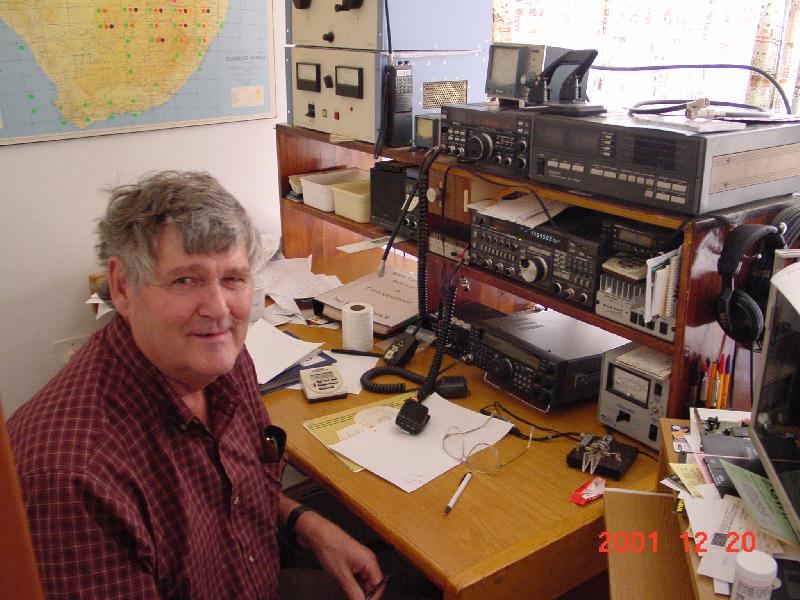
Hal Lund ZS6WB, my neighbour, often ended up helping with all those last-minute projects, just before the contest weekend. The picture shows Hal at his operating desk, surrounded by countless little knobs. I'm just happy that my station is simple, and I don't have to deal with all those buttons! If you're wondering about the pained expression, don't blame me. The picture was taken by ZS4TX (2001-12)!
Jan van Niekerk ZS6NW (now N3NW in Texas) contributed substantial logistics in the early days. Many of the towers have his name on them.
Danie Brynard ZS6AWK spent a huge amount of time helping me tune the 80 m beam. It's not a project you would want to tackle lightly! Each element went up and down the tower half a dozen times, as did the entire beam. The beam weighs around 100 kg.
Tjerk Lammers ZS6P had a great workshop at his business premises, and did much of the machining on the industrial-grade chain drives that turn the big stacks. Some creative machining was needed, as the chain drives had to be added after the fact on the low band tower, when the rotor couldn't cope with the original drive design.
Jan Grobbelaar spent much time over the years helping me think through mechanical design aspects. Both of us are electronics engineers, with little more than a lively interest in things mechanical and some basic mathematics to see us through. Jan even helped me to make the modifications on the low band tower's rotator plate. He still speaks about the event in hushed tones!
Others have come and gone, and helped with slave labour and the odd bit of support. Examples include G3MXJ, ZS6AL, ZS6CAX, ZS6IR, ZS6PJS, ZS6RI and ZS6UT.
Some of my guest-ops have also helped with helpful comments, and by just allowing me to watch while the station was being used in anger. Not having to do anything myself allows me to think through the ergonomics a lot more clearly. Examples of guest operators include DK3GI, G3MXJ, JM1CAX (a.k.a. ZS6CAX and JY9NX), LX1NO, ON6TT, PA3DZN, ZS1EL, ZS6IR, ZS6NW, ZS6RI, ZS6WB and ZS8D.
Return to ZS6EZ's Radio Page